Transformer Testing Equipment
Transformer Test Bench Manufacturers In India
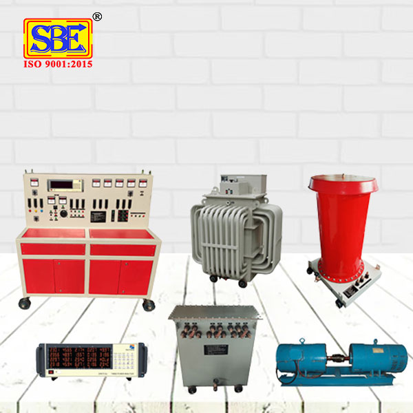
The product made from a top transformer test bench manufacturers occurs with A complete Common Test Bench to perform High Voltage Test, No Load Test (OC Test), Full Load Test (SC Test), Induced Over Voltage withstand Test (DVDF Test) to measure No Load & Full Load Losses, Efficiency, Impedance, Insulation and other electrical parameters . You will understand its input voltage, showing lamps, push buttons, HRC fuses, mode changing rotary switches, digital frequency meter, and voltmeter selector rotary switches. The panel of the transformer test bench also arrives with a voltage regulator, tripping arrangement, and metering to provide you with the latest information having reliable data. We assure you that your transformer will grant you the appropriate testing measurement that will help you create the ideal transformer machines and their equipment.
Download Catalogue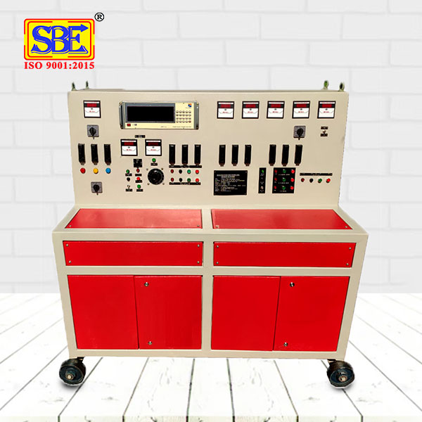
High Accuracy - Transformer Test Bench
The test bench for the transformer is made in such a way that it can give you the automatic tripping arrangement in the individual setup.
We are leading Transformer Test Bench Suppliers in India. The benefit of automatic tripping is it takes care of your distributed control system and safety instrumented system. Try the transformer test bench equipment now!
- Motor Generator Set.
- Fully Automatic Starter.
- Desk type CONTROL PANEL.
- Intermediate Auto Transformer.
- Three Phase Variable Auto Transformer.
- AC High Voltage Test Set for HT Testing.
- AC High voltage Test Set for LT Testing.
- Digital Meters will be provided for all parameters.
- Automatic Tripping arrangement will be provided in all Individual Setup.
- Digital Timer is provided along with ON-OFF Switch to set the Testing Duration Time.
A complete common Test Bench to perform No Load Test (OC Test), Full Load Test (SC Test), Induced Over Voltage with stand Test (DVDF Test), High voltage test for LT & HT, To measure NO load & Full Load Losses, Efficiency, Impedance, Insulation and other Electrical parameters of 3-Phase Distribution and Power Transformer ranging from 16 KVA to 50 MVA rating along with 3-Phase intermediate Transformer of Suitable capacity, 3-Phase Motorized variable auto transformer of suitable capacity :- 440 Volts Input & 0-470 Volt output, Motor Generator set of Slip Ring Motor & Induction Motor along with suitable contactors, Panel meters & Required accessories.
| Input | 415 V, 3 Phase, 4 Wire, 50 Hz A.C | ||
| For DVDF Test | 0 – 1000 V, 3 Ph. 100 Hz. At Four Different Taps. | ||
| For Load & No-Load (For Distribution Transformer) | 0 – 600 V 3 Phase, 50 Hz | ||
| For Load (For Power Transformer) | 0 – 3000 V 3 Phase, 50 Hz | ||
| For No-Load | 0 – 600 V 3 Phase, 50 Hz. | ||
| Duty | Intermittent |
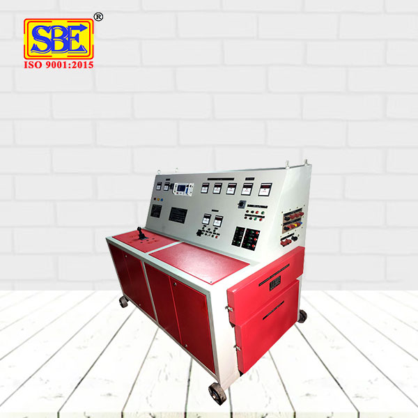
For DVDF & Load No-Load functionality, Control and the same Loading transformer unit along with the same variable motorized auto transformer are used. ( N.B. Generally, above 1 MVA, there comes into place an additional 3rd unit in the form of variable auto transformer. Above 3 MVA, the Loading Transformer comes into place as an additional 4th unit ). The inclined front panel has indicating lamps, HRC fuses, push buttons, mode changing rotary switches, voltmeter selector rotary switches, digital frequency meter ( for DVDF ) along with its toggle switch to indicate Input/output frequency and these are all part of ‘ Control unit’. 1 no.
Digital voltmeter of 96 sq.mm. is provided for Input voltage measurement and 1 no. Digital AC voltmeter of 96 sq.mm. for measuring the Output voltage. Besides these, 3 individual Digital ammeters of 96 sq.mm. are also connected to 3 different phases for measuring Output currents in the respective phases and all these meters are for DVDF purpose. For Power Frequency High Voltage Testing the Control Section along with Voltage Regulator, Metering & Tripping Arrangement are provide in the panel. For Load No-Load measurements, arrangements of One Three Phase Power Analyzer is given in the Panel. Mounted inside are current measuring CT’s, voltage measuring P.T’s ( for DVDF purpose ), contactors, automatic star- delta starters ( for DVDF ) , loading transformer, variable auto transformer ( if rating is above 1 MVA, the auto transformer will be treated as a separate unit as previously mentioned in nota-bene. ) 4 nos. casting wheels at the bottom of powder coated sturdy steel cabinet is provided for easy mobility. 4 nos. lifting hooks are also there for lifting purpose. All nomenclatures are engraved in anodized aluminum plates which are placed on the inclined front panel.
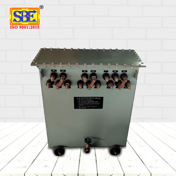
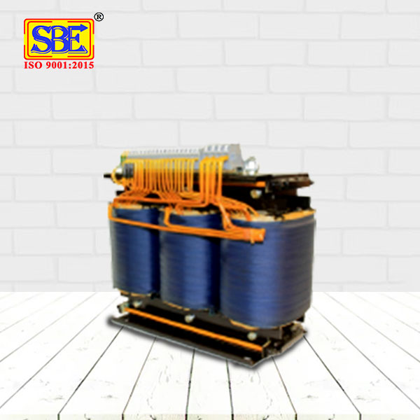
One Three Phase Intermediate Booster Transformer of Intermittent Rating is used to boost the Motor Generator Output Voltage to the desired voltage level for applying in the Transformer Under Test. Three phase Booster Transformer is used to give a Long Lasting Life Cycle to the Motor-Generator Set. High Quality Copper is used for winding of the Three Phase Intermediate Booster Transformer.
| Input | 415 V, 3 Phase, 4 Wire, 50 Hz A.C | ||
| For DVDF Test | 0 – 1000 V, 3 Ph. 100 Hz. At Four Different Taps. | ||
| For Load & No-Load (For Distribution Transformer) | 0 – 600 V 3 Phase, 50 Hz | ||
| For Load (For Power Transformer) | 0 – 3000 V 3 Phase, 50 Hz | ||
| For No-Load | 0 – 600 V 3 Phase, 50 Hz. | ||
| Duty | Intermittent | ||
| Cooling | Air Natural Cooled |
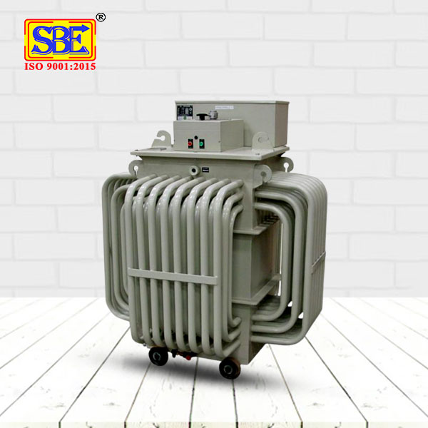
THREE PHASE VARIABLE AUTO TRANSFORMER is used to vary the Output Voltage continuously.
SALIENT FEATURES :-
- The drop in Voltage from “No Load to Full Load” is minimal.
- It provides an output voltage waveform, which is a distortion-less replica of the input voltage waveform.
- Careful Copper & Core selection and design assures the user of low watt loss, as compare to other controllers.
- A Glass smooth commutator, special sintered bushing for the shaft and perfect assembling of coils results in low operating torque for all Variable Auto Transformer.
- A special Silver Plating Technique is used on the Commutator, enabling it to withstand high overloads and maintain Proper contact . It also ensures smooth operation, long life & increased resistance to corrosion.
| Input | 440 V, 3 Phase-4 Wire,50 Hz, AC |
| Output | 0 – 470 V, 3 Phase, 50 Hz, AC |
| Capacity | As per system requirement. |
| Cooling | Air Natural Cooled / Oil Cooled |
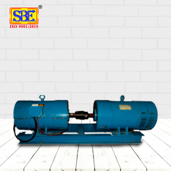
THREE PHASE MOTOR GENERATOR SET is used in TRANSFORMER TEST BENCH to perform Induced Over Voltage Test (Double Voltage Double Frequency Test). MOTOR GENERATOR SET is a combination of Three Phase Slip Ring Motor & Three Phase Induction Motor. It provides Variable Output Voltage Motor will be in Old Casing, Newly Winded & Heat Varnished to reduce the Voltage & give a Long Lasting Life time. Two Motors are Coupled with each other on a MS Channel Frame.
- For Squirrel Cage Motor UPTO 600 HP
- For Slip-Ring Motor UPTO 1200 HP
- Input : 415 V Three Phase, 50 Hz through Fully Automatic Starter.
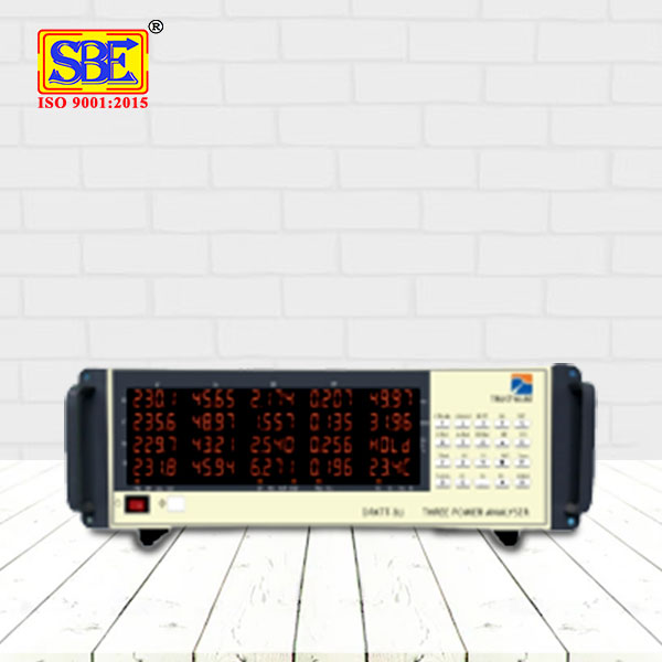
The Three Phase Power Analyzer Instrument is ingenuously designed and developed to make the testing of Stabilizers, Transformers ,Motors and other Electrical Machines Simpler , Faster, Accurate and Reliable with its high performing DSP based circuitry and user friendly operational features. The high speed simultaneous sampling of all the channels using 24-bit ADC ensures True RMS measurement of the wide range of input voltage and input current. This instrument displays Voltage, Current, Frequency, Active Power and Power Factor, both phase wise and Total/Average. The measurement is valid at all power factors and gives L in the presence of harmonics in the system.
| PARAMETERS | |||
| Voltage ( V) | V1,V2,V3 & Avg. Voltage | System Frequency | (Hz) |
| Current (A) | I1 , 12 , 13 & Avg. Current | Power Factor ( CosA ) | PF1, PF2, PF3 & System |
| Active Power (W) | W1,W2,W3 & Total Wattage | Apparent Power ( VA) | Total |
| Measurement | True RMS | Phase Current | 50mA – 80A AC |
| System Frequency | 40 to 70 Hz | For Power Factor | 0.05 Lead to unity to 0.05 Lag |
One Two phase (w.r.t. L.T.) Copper Double Wound H.V. Step-up Transformer comprises of the H.V. unit & The HV winding of the High Voltage testing transformer is of GRADED INSULATION. The Transformer will be Oil Natural Cooled and housed in an “Insulated Cylindrical Jacket” which is placed on M.S. Trolley. A metallic sheet is placed on the top of the Insulated Cylindrical Jacket through which an H.V. terminal is brought out. L.T terminals and starting end of H.V. coil is brought out at the bottom side of the M.S. Trolley marked as “L 1, L2 & V” respectively just below the Insulated Cylindrical Jacket.
| Input Voltage | 400 Volt, Two Phase (Of Three Phase), 50 Hz, Ac | ||
| Output Voltage | 0-80/100/120/150 KV | ||
| Leakage Current | 50/100/200/300/400/500/1000/2000/3000 select-able by Rotary Switch in steps. | ||
| Duty | Intermittent | ||
| Cooling | Oil Natural Cooling | ||

